
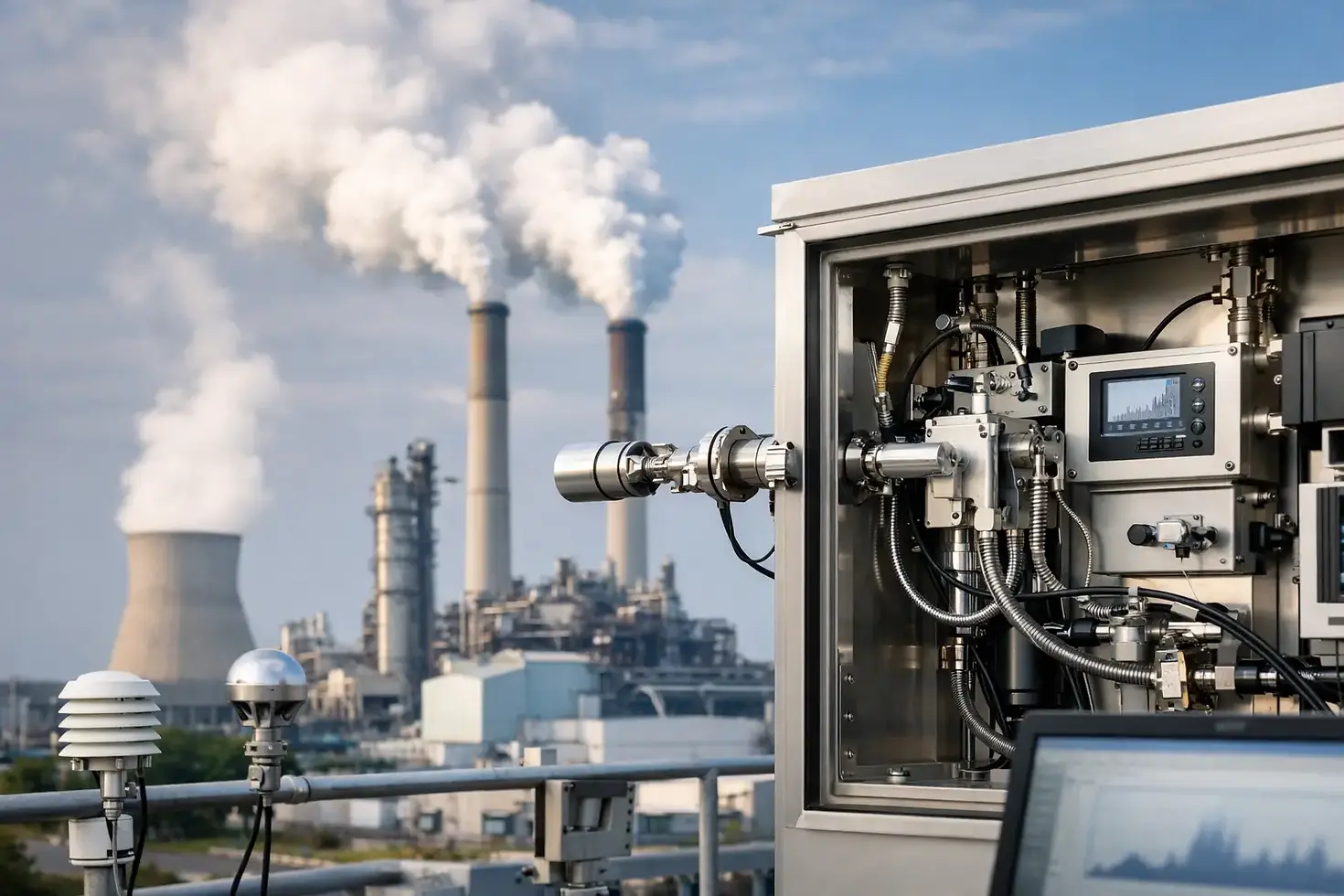
CEMS Technology for Defensible Emissions Data
A continuous emissions monitoring system is only as credible as the measurement program behind it. CEMS technology can provide near-real-time insight into stack emissions, but it does not eliminate the need for sound engineering, disciplined quality assurance, representative sampling, and documented maintenance. For facilities subject to permit limits, trading programs, or recurring emissions reports, those details determine whether the data is useful, defensible, and accepted by regulators.
CEMS are commonly applied to boilers, heaters, engines, kilns, turbines, incinerators, and other combustion or process sources where emissions must be monitored continuously or where operating conditions change too quickly for periodic testing alone. The right system supports compliance reporting while also giving plant personnel earlier warning of combustion, control equipment, or fuel-related issues.
What CEMS Technology Measures
CEMS technology is a coordinated system of analyzers, sampling equipment, calibration components, data acquisition, and quality-control procedures. It measures one or more pollutant concentrations in flue gas and, where required, determines stack gas flow, moisture, oxygen, carbon dioxide, or other parameters needed to calculate emissions rates.
Typical monitored constituents include nitrogen oxides (NOx), sulfur dioxide (SO2), carbon monoxide (CO), carbon dioxide (CO2), oxygen (O2), hydrogen chloride, ammonia, total hydrocarbons, particulate matter, and mercury. The required parameters depend on the source, fuel, permit conditions, applicable regulations, and reporting program. A gas-fired unit may require a different configuration than a cement kiln or diesel engine, even when both report NOx.
The system generally uses one of two measurement approaches. Extractive CEMS withdraws a conditioned sample from the stack, transports it through a heated line or sample conditioning system, and measures it in an analyzer cabinet. This approach can support a broad range of analyzer technologies and allows controlled sample treatment, but it introduces components that require careful maintenance, including probes, filters, pumps, dryers, and heated lines.
In-situ CEMS measures directly in the stack or duct. It can reduce sample transport concerns and response time, but optical alignment, window fouling, path length, temperature, pressure, and gas stratification must be considered. Neither approach is automatically better. The appropriate design depends on the pollutant, stack conditions, moisture level, available access, required accuracy, and the facility's ability to maintain the equipment.
CEMS Technology Is a Compliance System, Not Just an Analyzer
A common procurement mistake is to evaluate CEMS technology as an analyzer purchase. The analyzer matters, but it is only one element of a compliance-grade system. A complete installation must establish that the measured gas is representative of the stack stream, that the instrument is calibrated and operating within allowable performance criteria, and that recorded data is processed according to the governing rule or permit.
For sources governed by U.S. EPA requirements, the relevant framework may include Performance Specifications, 40 CFR Part 60 Appendix B, Part 75, or method-specific requirements. Canadian facilities may be subject to federal or provincial approvals, emissions trading requirements, or facility-specific monitoring and reporting conditions. In every case, the permit and program requirements should drive the design basis.
That design basis should identify the emission limits, averaging periods, reporting units, required pollutants, expected concentration range, and data availability obligation. It should also define how diluent corrections, moisture corrections, stack flow, and heat input will be handled. These decisions affect not only the equipment selection but also the calculations used to demonstrate compliance.
For example, measuring dry-basis NOx concentration may be sufficient for one permit condition. Another may require NOx mass emissions in pounds per hour, tons per year, or a heat-input-based rate. That second case may require reliable flow, fuel, heat input, moisture, and diluent data in addition to the pollutant analyzer result.
Sampling Location and Installation Drive Data Quality
An analyzer cannot correct for a poor sampling location. Before selecting equipment, engineering teams should evaluate the stack geometry, duct dimensions, flow profile, access platforms, temperature, pressure, moisture, particulate loading, and potential for stratification. A location downstream of a control device may be necessary to demonstrate controlled emissions, but that same location may present condensation, corrosion, or access challenges.
Representative sampling is particularly important where emissions are nonuniform across the duct. Sources with multiple burners, complex ductwork, recirculation, dampers, or pollutant injection can produce concentration gradients. A single-point probe may not represent the average gas stream under all operating conditions. In those cases, a multi-point probe, cross-duct measurement, or additional evaluation may be justified.
Installation planning should also address practical operating needs. Technicians need safe access for routine inspections, calibration gas replacement, filter changes, and troubleshooting. Electrical classification, weather protection, trace heating, instrument air, sample line routing, shelter ventilation, and communications must be resolved before commissioning. Deferring these details often results in avoidable downtime and difficult maintenance.
Quality Assurance Makes Continuous Data Defensible
Continuous monitoring produces a large volume of data, but quantity is not the same as quality. A credible CEMS program includes routine calibration checks, preventive maintenance, operational audits, and periodic performance testing against a recognized reference method.
Daily or routine zero and upscale calibration checks verify that the analyzer responds within acceptable limits. Drift results should be reviewed rather than simply recorded. Repeated drift can indicate deteriorating components, contaminated optical surfaces, unstable sample conditioning, leaks, regulator problems, or calibration gas issues. Correcting the cause early is usually less disruptive than waiting for a failed audit or extended outage.
Relative accuracy testing compares CEMS results with concurrent manual reference method testing. This is a critical validation step because it evaluates the system as installed, including sample extraction, conditioning, analysis, and data handling. A system can pass an internal calibration check while still disagreeing with reference measurements if the sample is not representative or if a calculation parameter is incorrect.
Data acquisition and handling systems also require controls. The system should apply the correct units, averaging rules, diluent corrections, substitutions, calibration flags, and invalid-data codes. Environmental managers should be able to trace a reported value back to raw readings, calibration records, maintenance logs, and the applicable calculation logic. That traceability is essential during inspections, audits, permit renewals, and internal reviews.
Operating Data Can Improve Plant Decisions
When properly maintained, CEMS data has value beyond meeting a reporting obligation. Shifts in CO and O2 can indicate combustion inefficiency, excess air changes, burner imbalance, or fuel variability. Rising NOx may point to changes in combustion temperature, load, staging, or control equipment performance. SO2 trends can reflect fuel sulfur changes or scrubber performance.
These operational uses require caution. CEMS data should be interpreted alongside load, fuel flow, process conditions, control device parameters, and maintenance activity. A short-term spike may be a real process event, a calibration period, an instrument fault, or a data processing issue. Establishing review procedures helps personnel distinguish meaningful emissions trends from instrument noise.
The trade-off is clear: a more comprehensive monitoring configuration can provide better operational insight, but it also increases capital cost, maintenance requirements, and the number of potential failure points. The best system is not necessarily the one with the most measurements. It is the one that reliably meets the facility's compliance obligations and produces data that operators can use.
A Practical Path for CEMS Projects
A successful project starts with a regulatory and technical gap assessment. Review current permit conditions, reporting commitments, historical testing data, stack drawings, fuel information, process changes, and existing instrumentation. This establishes whether continuous monitoring is required, what parameters must be measured, and whether the current stack configuration can support a representative installation.
Next, develop a specification that addresses the whole monitoring system: sampling approach, analyzer range, materials of construction, calibration equipment, data acquisition, communications, environmental protection, safety access, and required performance tests. Avoid specifications that focus only on analyzer detection limits while overlooking serviceability and data management.
Commissioning should include installation verification, leak checks, calibration response testing, data system configuration, operating procedure development, and initial performance testing. Plant personnel should understand what normal operation looks like, how to recognize invalid data, and when to involve qualified technicians. A maintenance plan should define routine tasks, critical spares, calibration gas management, response expectations, and documentation requirements.
Air Research Group supports industrial facilities with emissions measurement, CEMS-related technical services, equipment support, and compliance-focused field execution. Coordinating monitoring requirements with stack testing and reporting obligations can reduce gaps between field measurements, continuous data, and regulatory submissions.
A CEMS program earns confidence over time. Facilities that treat it as a managed measurement system - with qualified installation, routine verification, traceable records, and timely corrective action - are better positioned to defend their emissions data when it matters most.


Comments