
How to Calibrate Portable Gas Analyzers Correctly
A portable analyzer that reads within specification in the shop can still produce unusable data at the stack if it is zeroed incorrectly, supplied with expired calibration gas, or affected by a restricted sample path. To calibrate portable gas analyzers correctly, a facility needs more than a quick span check before leaving for the field. It needs a documented process that accounts for the instrument, the gas standard, the sampling system, and the measurement objective.
For emissions testing, combustion optimization, regulatory reporting, and troubleshooting, analyzer calibration is a data-quality control. A poor calibration can lead to incorrect oxygen correction, distorted pollutant concentrations, missed operating issues, and emissions results that cannot be defended during a compliance review.
What Calibration Must Confirm
Calibration establishes the relationship between the analyzer response and known reference concentrations. For a portable flue gas analyzer, this typically includes a zero adjustment and one or more span adjustments for measured components such as oxygen, carbon monoxide, carbon dioxide, nitrogen oxides, sulfur dioxide, hydrocarbons, or other application-specific gases.
The correct approach depends on the analyzer design and the required method. Electrochemical sensors, nondispersive infrared detectors, paramagnetic oxygen cells, flame ionization detectors, and chemiluminescence analyzers do not behave identically. Their warm-up requirements, response times, interference risks, and calibration ranges must be evaluated according to the manufacturer’s instructions and the governing test method or site quality plan.
Calibration does not prove that the full sampling train is functioning properly. A properly adjusted analyzer can still report biased values if the probe is leaking, the filter is loaded, the heated line is not maintaining temperature, condensate has reached the instrument, or sample flow is inadequate. For field work, the analyzer and sample-conditioning system must be treated as one measurement system.
Calibrate Portable Gas Analyzers Before Field Use
Begin before the instrument is connected to the source. Verify that the analyzer has completed its required warm-up period and that its battery or external power supply will support the full test duration. Confirm the operating range, sensor condition, pump performance, filter status, and date of the last preventive maintenance service.
The calibration gases must be traceable, within expiration, and appropriate for the expected concentration range. A span gas that is far above or below the expected measurement range can reduce the value of the check, even when the analyzer accepts the adjustment. Select concentrations that meet the applicable method requirements and provide meaningful confirmation of the ranges expected during the test.
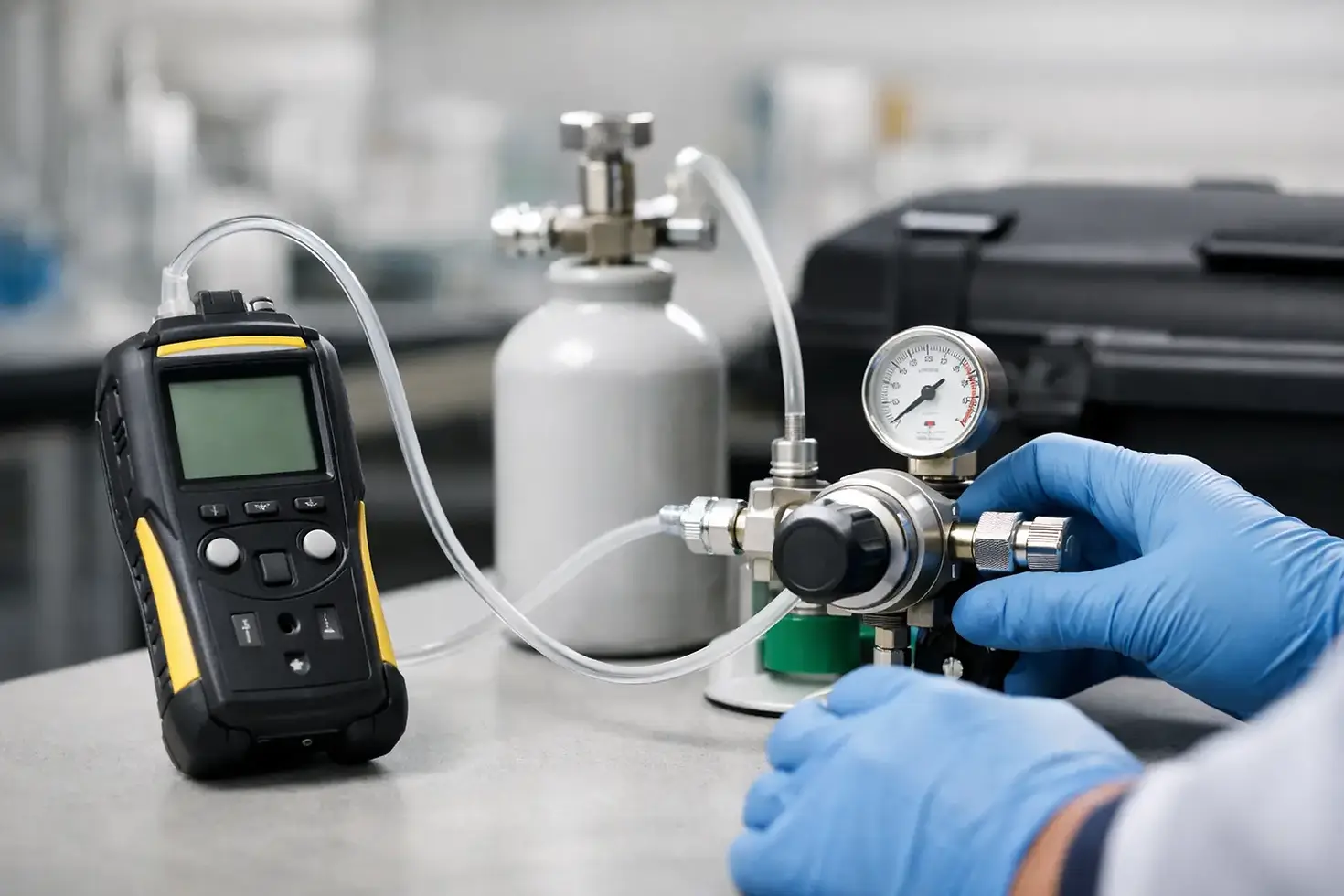
The regulator, tubing, fittings, and calibration adapter also matter. Use clean, compatible materials and maintain stable flow at the rate specified for the analyzer. Reactive gases such as nitrogen dioxide, sulfur dioxide, hydrogen sulfide, and ammonia may be affected by adsorption or inappropriate wetted materials. Short, properly conditioned lines help reduce losses and improve response consistency.
Before introducing calibration gas, inspect the setup for obvious leaks and restrictions. A leak on the calibration side can dilute the gas and create a false low response. A restriction can alter flow and delay stabilization. Neither condition should be corrected by simply adjusting the span value.
Zero the Instrument With the Correct Gas
Zero gas establishes the baseline response. Depending on the analyzer and measurement program, this may be high-purity nitrogen, clean dry air, or conditioned ambient air. The correct choice is not interchangeable. For example, an oxygen channel may require a different zeroing approach than a carbon monoxide or nitrogen oxides channel.
Allow the reading to stabilize before accepting the zero. A fast adjustment may save minutes but can introduce drift into the entire test run. Record the zero-gas identity, cylinder number where applicable, flow setting, time, and final readings. If the instrument cannot reach or hold zero, investigate the cause before proceeding. Common causes include sensor degradation, contaminated filters, residual gas in the sample path, leaks, or inadequate warm-up.
Apply Span Gas and Verify Response
Introduce the certified span gas at the manufacturer-specified flow rate. Let the instrument response stabilize, then compare the reading with the certified concentration. If the analyzer is within the established acceptance criteria, document the as-found result. If adjustment is permitted and necessary, make the span adjustment and document both the pre-adjustment and post-adjustment values.
Avoid treating calibration as a pass-or-fail button press. The as-found response is valuable information. A growing difference between the certified value and the analyzer reading can indicate sensor aging, optical contamination, a developing leak, or an instrument that requires service. Trend records often identify problems before they create a failed field test or invalid compliance data.
Distinguish a Bump Test From a Full Calibration
A bump test is a functional check that confirms the sensor responds to a known gas. It is commonly used for personal gas monitors and may be appropriate as a daily readiness check for certain portable instruments. It does not necessarily verify accuracy across the measurement range or establish a valid zero and span adjustment.
A full calibration includes the required zero and span procedures, stabilization, acceptance review, and documentation. For compliance-related emissions measurements, the governing method, permit condition, protocol, or quality assurance plan should define the required frequency and performance criteria.
The practical distinction matters. A technician may see a response during a bump test and assume the analyzer is fit for emissions work. If the response is significantly biased, however, the analyzer may identify the presence of a gas while still reporting an incorrect concentration. That can affect combustion decisions and regulatory calculations alike.
Control the Factors That Cause Field Drift
Calibration at the start of the day is not always enough. Portable analyzers are exposed to temperature changes, vibration, moisture, high concentrations, and long sampling periods. These conditions can cause drift or change sample transport behavior.
A disciplined field program includes post-test calibration checks. After sampling, repeat the applicable zero and span checks and compare the results with acceptance limits. A failed post-test check may trigger data review, corrective action, or retesting, depending on the method and the magnitude of the deviation. It is better to identify this result immediately than to discover it after reporting deadlines approach.
Moisture management deserves particular attention in flue gas work. Condensation can remove water-soluble gases from the sample, damage sensors, and create unstable readings. Heated probes and lines, properly maintained condensate traps, filters, and dryers must be selected and operated in a way that supports the target analytes and the required test method. Removing moisture can be necessary, but it may also affect soluble components if the system is not designed for that purpose.
Interference is another frequent source of error. Cross-sensitivity data from the analyzer manufacturer should be reviewed when significant concentrations of other gases are expected. Oxygen, carbon dioxide, water vapor, hydrocarbons, sulfur compounds, and nitrogen oxides can affect certain sensor technologies differently. A calibration gas confirms response to the target analyte, but it may not reproduce the complete source-gas matrix.
Documentation Makes Results Defensible
Calibration records should allow a qualified reviewer to reconstruct what occurred before, during, and after a test. At minimum, retain the analyzer identification, sensor or module identification where relevant, calibration gas certificates and expiration dates, zero and span results, adjustment records, acceptance criteria, flow settings, technician name, and timestamps.
For formal emissions programs, also retain instrument maintenance history, leak-check records, sample system configuration, field logs, and any deviations from the planned procedure. These records support internal quality review and provide evidence that reported emissions values were generated through controlled measurement practices.
A clear record also improves operational efficiency. If an analyzer begins failing span checks after a specific number of hours or only during cold-weather work, maintenance teams can investigate the pattern instead of responding to each issue as an isolated event.
When Calibration Cannot Correct the Problem
Repeated adjustment is not a repair strategy. If an analyzer will not stabilize, fails a post-calibration check, shows excessive drift, has slow response, or requires frequent large adjustments, remove it from compliance service until the issue is evaluated. Continuing to use a questionable instrument can cost more than the downtime it was intended to avoid.
The appropriate corrective action may be sensor replacement, optical cleaning, pump repair, leak repair, regulator replacement, sample-line maintenance, or factory-level service. After repair, verify performance using the applicable calibration procedure before returning the analyzer to field duty.
For facilities managing recurring stack tests, combustion studies, or continuous compliance obligations, a defined calibration and maintenance schedule turns portable analyzers into dependable measurement assets rather than uncertain field tools. Air Research Group supports this work through analyzer calibration, repair, and emissions measurement services aligned with the technical and documentation demands of industrial compliance programs.
The most useful calibration program is the one that detects uncertainty before it reaches a report, a permit calculation, or an operating decision. Treat every zero, span, and post-test check as evidence that the numbers being used to manage emissions are numbers the facility can stand behind.


Comments